
GC capillary column care is the control of three failure modes: mechanical damage to the fused-silica tube and its polyimide coating; contamination of the inlet end by nonvolatile sample residue; and chemical degradation of the polysiloxane stationary phase by oxygen and heat. Column life is decided by leak-tight installation, oxygen-free carrier gas, operation within the phase’s temperature limits and inlet hygiene, not by a calendar.1,2
Contamination shows as tailing and is trimmed away; phase degradation shows as bleed and is irreversible; mechanical damage is prevented, or at best patched with a union. This page gives the chemistry of each, a checklist (Table 1), the bakeout–trimming–replacement distinction and a troubleshooting matrix (Table 2).
Chromatography Troubleshooting Decision Engine
Any HPLC symptom, one starting point — the engine narrows hundreds of failure modes to the few that fit your evidence.
What damages a GC capillary column?
A wall-coated open-tubular (WCOT) column is a fused-silica capillary with a cross-linked polysiloxane or polyethylene glycol film inside and a polyimide coating outside. Fused silica is strong only while its surface is flawless; the polyimide protects it from abrasion, and a scored section is where it breaks.1,3 Standard polyimide limits the tube to about 360 °C, with brief excursions to about 400 °C tolerated; most phases are rated lower, so the phase limit usually governs.3,4
The phase fails chemically by two routes. Under heat alone a polydimethylsiloxane chain folds back on itself and the Si–O backbone rearranges intramolecularly (‘backbiting’) into cyclic siloxanes, the trimer D3 most abundant, with a competing radical route at higher temperature.5 The GC-MS bleed spectrum is therefore dominated by m/z 207 and 281, the base peaks of D3 and D4; septum bleed instead gives a base peak at m/z 73.6 Oxygen opens the second route, oxidation, which begins just above room temperature and grows more severe with temperature; prolonged oxygen exposure is the most destructive and most common mode of column failure.1
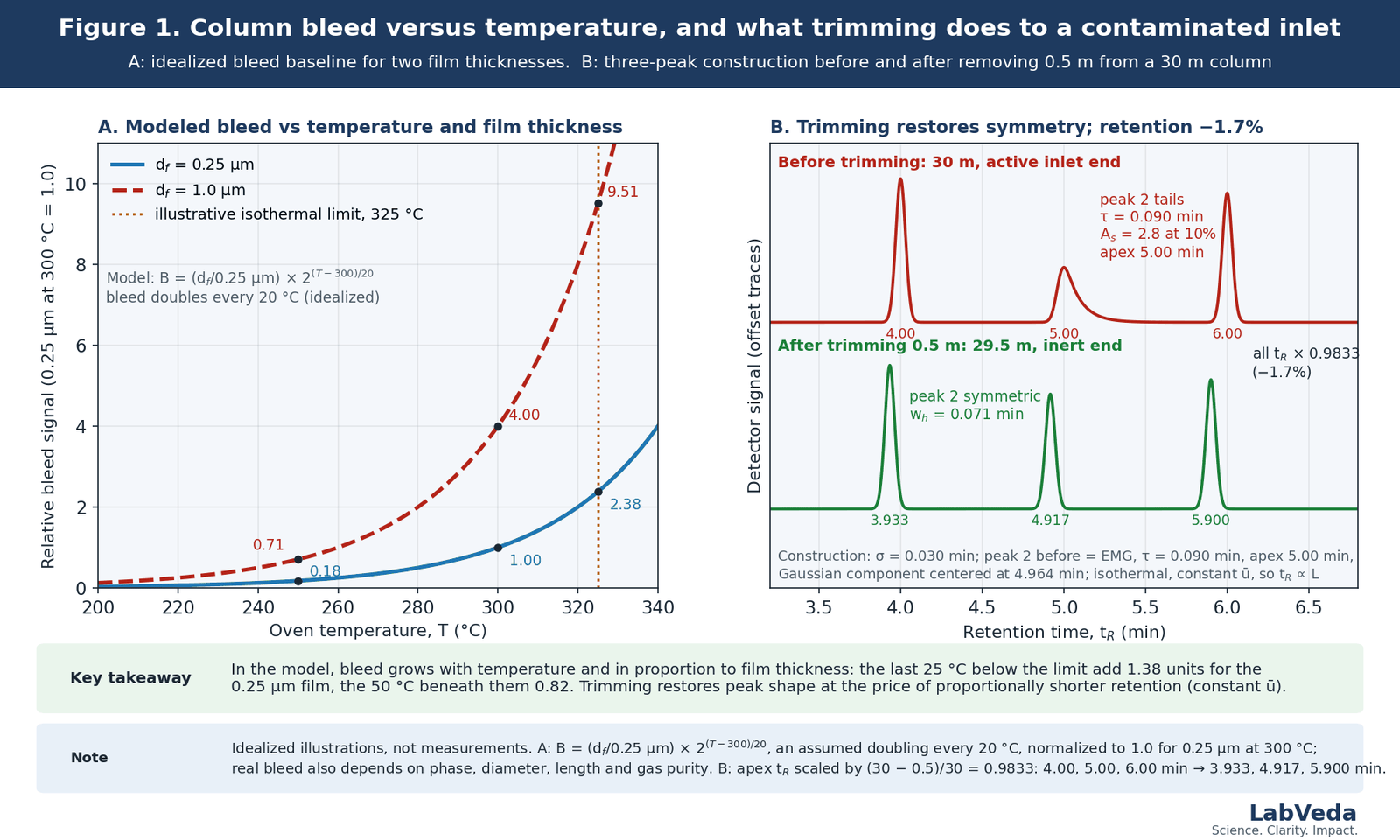
Bleed is present on every column and climbs steeply (Arrhenius-like) with temperature and in proportion to the phase exposed: higher for thicker films, wider bores, longer columns and more polar phases, lowest for a thin-film, low-polarity phase of a manufacturer’s low-bleed grade.1,7 Figure 1A models this for two film thicknesses; Table 1 is the checklist.
| Stage | Practice | Risk controlled |
|---|---|---|
| Installation | Square cut; specified ferrule and insertion depth; electronic leak check, repeated after first heating | Oxygen ingress, dead volume, breakage |
| Carrier gas | High-purity gas; oxygen trap plus indicating trap; leak check after any disturbed fitting | Oxidative phase loss, bleed |
| Conditioning | Carrier purge before heating; hold within the isothermal limit until the baseline is flat | Oxygen damage while hot, initial bleed |
| Routine operation | Program only as hot as needed; programmed limit only for short final holds | Accelerated phase loss, polyimide embrittlement |
| Sample and inlet hygiene | Cleanup of nonvolatile matrix; scheduled liner and septum changes; guard column for dirty samples | Inlet contamination, tailing, ghost peaks |
| Recovery | Trim the inlet end when evidence points there; bake out only for semivolatile residue; retest with a standard | Needless replacement, thermal damage |
| Storage | Cool, remove without kinking, cap both ends, keep in the cage | Air and moisture ingress, abrasion |
How should a GC column be installed and leak-checked?
Cut the end square with a ceramic, sapphire or diamond tool and inspect it under a lens; a ragged end or polyimide fragments give a mixing volume and adsorptive sites that broaden and tail peaks.8 Insertion depth depends on the inlet and detector type and comes from the instrument manual; on the detector side the flame ionization detector guide covers what a column set too high or too low costs.8,9
A graphite or polyimide-graphite ferrule relaxes after the first oven cycle and should be retightened and re-checked once.8 Leak-check with an electronic detector, never with a soap solution.1,8 An inlet-fitting leak admits oxygen directly to the hot column; a detector-fitting leak raises noise and, on a mass spectrometer, the air and water background.8 Removal reverses the sequence: cool, loosen, withdraw without kinking, cap both ends, return to the cage.1
Why do carrier gas purity and an oxygen trap matter?
Oxygen damage is cumulative and comes from the supply and from leaks. One manufacturer specifies carrier purity of 99.995% or better with oxygen below 1 ppm,9 and Jones and colleagues recommend a large-capacity trap followed by a small self-indicating trap at the instrument.1 A trap cannot compensate for a leaking fitting downstream of it, so leak-checking remains the primary control; polyethylene glycol phases are notably oxygen-sensitive.2 Hydrogen carrier is flammable, and the laboratory should review the hydrogen safety equipment and procedures the instrument manufacturer specifies before adopting it.10
How is a new GC column conditioned, and is there a universal schedule?
There is no universal schedule; the manufacturer’s instructions for the specific phase take precedence. The shared order is to connect the inlet end only, purge with carrier before heating so that air is displaced (10–20 min in Jones and colleagues’ re-conditioning procedure, 15 min in one manufacturer’s), then ramp and hold until the baseline is flat under the intended detector.1,9 As a working rule the conditioning temperature is 10–20 °C above the method maximum or the isothermal limit, whichever is lower, and a flat baseline typically arrives within 1–3 h.9 Manufacturers publish an isothermal limit, at which the column can be held for a prolonged time, and a programmed limit somewhat above it, tolerated for a few minutes at the end of a run; the pair is 325/350 °C for one (5%-phenyl)-methylpolysiloxane column, and the gap varies by phase.9,11 Conditioning beyond a stable baseline is consumed column life.2
How do inlet contamination, guard columns and retention gaps affect column life?
Nonvolatile residue accumulates in the first centimeters of the column, creating active sites that adsorb polar analytes and catalyze decomposition; the symptoms are tailing, lost response for labile compounds, ghost peaks and background.2,7 Prevention is sample cleanup, sensible injection volumes and split ratios and scheduled liner replacement, because a contaminated liner seeds the column head.7
A retention gap is an uncoated, deactivated length of fused silica ahead of the analytical column, introduced by Grob to refocus bands spread along the column entrance by solvent flooding in splitless and on-column injection (‘band broadening in space’).12,13 The same section doubles as a sacrificial trap for nonvolatile residue, trimmed or replaced without touching the analytical column; as a working rule, 3–5 m of deactivated tubing serves as a guard for dirty samples.1,7
Bakeout, trimming or replacement: which column maintenance fixes what?
The three interventions address different failure modes. A bakeout near the isothermal limit under carrier flow elutes semivolatile residue; it cannot remove nonvolatile matrix or restore oxidized phase and, done often, accelerates the degradation it is meant to cure, so it is never run with a suspected leak. Trimming removes the active inlet section: as a working rule 10–20 cm with each liner change, and up to about 1 m on a column longer than 20 m without major loss of resolution, retesting after each cut. Replacement is for bleed that stays high after a leak-free bakeout, phase degraded along its length, or cumulative trimming that has shifted the method; it does not fix an inlet, gas or method fault, which recurs on the new column.1,2
What does trimming cost in retention?
Under isothermal conditions at constant average linear velocity ū, every retention time scales with length, because the hold-up time is tM = L/ū and the IUPAC retention time is tR = tM(1 + k) with the retention factor k unchanged.14 Removing 0.5 m from a 30 m column gives
L′/L = (30 − 0.5)/30 = 0.9833, so tR falls by 1.7%
where L′ is the trimmed length: a peak at 5.00 min moves to 4.917 min (Figure 1B). That holds at constant ū, in practice constant-flow control with the new length entered. At constant inlet pressure, or in constant-flow mode with the old length still entered, tM scales with L², so the shift is about twice as large, 1 − 0.9833² = 3.3% here; in a temperature-programmed run late peaks shift less than proportionally. A 10–20 cm trim costs 0.3–0.7% at constant ū on a 30 m column, which is why the cumulative trim belongs in the maintenance record.1
Which GC troubleshooting symptoms point to the column?
Table 2 lists column-related possibilities; inlet, pneumatic, detector and method faults imitate every one of them, so establish the pattern with the GC troubleshooting guide first. The discriminating experiment is a test mixture run under fixed conditions and compared with the installation record.15
| Symptom | Column-related possibilities | Discriminating check and action |
|---|---|---|
| Tailing of active analytes | Contaminated inlet end; ragged cut or liner particles | Test mixture with an active probe; inspect liner and cut; trim 10–20 cm and retest |
| Bleed and background climbing; m/z 207/281 in blanks | Oven above the isothermal limit; oxygen from a leak or exhausted trap; aged phase | Leak-check; verify the phase limit; replace the trap; replace the column only if bleed stays high after a leak-free bakeout |
| Retention shift | Flow or pressure change; leak; old length still entered after a trim; phase loss | Verify flow and entered length first; after a trim, isothermal retention shifts in proportion to length at constant ū, about twice that at constant pressure |
| Ghost peaks | Carryover; retained matrix; septum bleed (base peak m/z 73) | Blank sequence; inlet maintenance; bakeout only if the residue is semivolatile |
| Broad peaks, low efficiency | Poor installation; dead volume at a fitting; flow off optimum; physical damage | Check insertion depth and cut; measure ū with an unretained compound (tM, see the chromatography terms glossary) |
What belongs in a GC column maintenance record?
Record the column identity and dimensions, installation date, entered length after every trim and cumulative length removed, liner, septum and trap changes, leak-test results, each conditioning or bakeout with temperature and duration, any excursion above the isothermal limit, and the test-mixture retention times and peak shapes at installation and at intervals. The log is the first thing to consult when a signal changes: it lets a retention shift be tested against the entered length and a tailing peak be dated to a liner change.15
Frequently asked questions
What is column bleed in GC?
Column bleed is the continuous, low-level loss of stationary-phase fragments into the carrier gas, seen as a baseline that rises with oven temperature and, in GC-MS, as the cyclic siloxane ions. It is a fault only when it exceeds the level recorded at installation, so the test is a blank run to the method’s final temperature, kept on file and repeated whenever the baseline is questioned.
When should I trim a GC column rather than replace it?
Trim when the evidence localizes the problem to the inlet end: tailing or lost response for labile analytes after dirty samples, with bleed unchanged and the liner also contaminated. Remove 10–20 cm, enter the new length and retest with the same standard, expecting an isothermal shift proportional to the length removed at constant ū. If two conservative trims do not restore peak shape, the activity extends further than a trim reaches; replace.
Can I condition a column at its maximum temperature overnight?
No, not as a routine. Conditioning ends when the baseline is flat under the intended detector, typically within 1–3 h; the rest of the night is phase loss without benefit. A column that has been solvent-rinsed or stored open may need a longer hold to clear residue, and even then the hold stays at or below the isothermal limit.
Do solvents such as acetonitrile or THF damage the stationary phase?
Not in general. Cross-linked, surface-bonded polysiloxane phases are stable to the common injection solvents, and many columns are specified as solvent-rinsable; Jones and colleagues describe rinsing followed by a 30 min nitrogen purge before re-conditioning.1 What damages the phase is what the solvent carries in: nonvolatile matrix, strong acids or bases and derivatization reagents that attack the phase or its deactivation layer. Check the phase’s compatibility statement.
Which limit applies, the polyimide’s or the phase’s?
The lower of the two. The polyimide coating caps the fused-silica tube at about 360 °C whatever the phase; most phases are rated below that, so the phase’s isothermal and programmed limits are the ones the method must respect. Only high-temperature phases approach the coating limit, and those are supplied on high-temperature polyimide or metal-clad tubing so the tube is not the weaker element.
The takeaway
A capillary GC column is lost to oxygen on a hot phase, nonvolatile residue at the inlet end and mechanical damage to the polyimide, and none of the three is reversed by heating harder. Install with a square cut, the specified insertion depth and an electronic leak check; keep oxygen out; condition and program only as hot as the baseline requires; and when performance falls, let the symptom, checked against the maintenance record, choose between trimming, bakeout and replacement.
References
- S. Jones, A. K. Vickers and M. Sinnott, “Practical Guidelines in the Care and Maintenance of Capillary GC Columns”, LCGC Europe 20(7) (2007).
- J. V. Hinshaw, “GC Column Degradation”, GC Connections, LCGC E-Separation Solutions, updated 9 November 2009.
- J. V. Hinshaw, “The Making of a Column”, GC Connections, LCGC North America 23(9) (2005).
- N. H. Snow, “Hard-Won Lessons in GC”, LCGC Europe 34(7) (2021).
- G. Camino, S. M. Lomakin and M. Lageard, “Thermal polydimethylsiloxane degradation. Part 2. The degradation mechanisms”, Polymer 43(7), 2011–2015 (2002).
- C. English, “Understanding the Origins of Siloxane Ghost Peaks in Gas Chromatography”, The Column (LCGC) 18(6), 10–15 (2022).
- J. V. Hinshaw, “GC Column Bleed”, GC Connections, LCGC E-Separation Solutions, updated 6 August 2010.
- J. V. Hinshaw, “Making a Great Connection”, GC Connections, LCGC North America 24(7) (2006).
- Agilent Technologies, Quick Reference Guide: Agilent J&W Capillary GC Columns — Installation, publication 5994-5240EN, agilent.com, updated 18 May 2023 (manufacturer-specific purge time, conditioning temperature and gas-purity specification).
- J. V. Hinshaw, “Frequently Asked Questions about Hydrogen Carrier Gas”, GC Connections, LCGC Europe 22(1) (2009).
- Agilent Technologies, DB-5ms EVDX GC column, temperature range −60 °C to 325/350 °C, product page, agilent.com, accessed 13 September 2026 (manufacturer-specific isothermal/programmed limit pair).
- K. Grob Jr., “‘Band broadening in space’ and the ‘retention gap’ in capillary gas chromatography”, J. Chromatogr. 237, 15–23 (1982).
- K. Grob and B. Schilling, “Uncoated capillary column inlets (retention gaps) in gas chromatography”, J. Chromatogr. 391, 3–18 (1987).
- L. S. Ettre, “Nomenclature for chromatography (IUPAC Recommendations 1993)”, Pure Appl. Chem. 65(4), 819–872 (1993).
- N. H. Snow, “Stopping GC and GC–MS Problems Before They Start”, LCGC North America 37(1) (2019).
Further reading
- R. L. Grob and E. F. Barry (eds.), Modern Practice of Gas Chromatography, 4th ed., Wiley (2004).
- D. Rood, The Troubleshooting and Maintenance Guide for Gas Chromatographers, 4th ed., Wiley-VCH (2007).
- H. M. McNair, J. M. Miller and N. H. Snow, Basic Gas Chromatography, 3rd ed., Wiley (2019).
Reviewed against primary sources. Every definition, mechanism and working rule on this page is checked against the 1993 IUPAC recommendations on chromatographic nomenclature and against the primary literature cited above; manufacturer documentation is cited only for manufacturer-specific limits and procedures. Numerical examples are illustrative calculations from the models stated and are not method-development predictions or acceptance criteria. For validated or compendial methods, the applicable procedure and regulatory framework take precedence over the general rules of thumb given here. Evidence review: September 2026.