
A flame ionization detector burns column effluent in a hydrogen–air flame and measures the tiny electrical current produced by the ions that form. The current is proportional to the mass of carbon reaching the flame, which makes the FID the closest thing gas chromatography has to a universal detector for organic compounds.
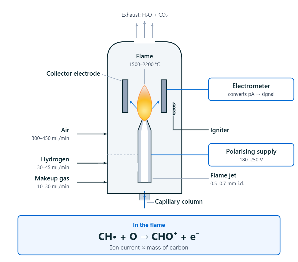
It is also the detector most people learn first and understand least. This page covers the ionisation mechanism, the compounds an FID is effectively blind to, the effective carbon number concept that lets you predict response without a standard, the gas flows and setpoints that actually matter, and a diagnostic path for the three failures you will meet in practice. Figure 1 shows the detector in cross-section.
How an FID actually produces a signal
Carrier gas leaves the column and enters the base of the detector, where it mixes with hydrogen and, usually, a makeup gas. The mixture passes up through a narrow flame jet and is burned in a stream of air just above the jet tip. The flame sits somewhere between 1,500 °C and 2,200 °C — hot enough to crack organic molecules apart completely.
The ionisation itself is not thermal. Combustion of a hydrocarbon proceeds through a radical chain, and the species that matters is the ground-state CH radical, which is produced in proportion to the carbon content of the molecule. That radical reacts with atomic oxygen:
CH• + O → CHO+ + e−
This single reaction is the FID’s entire signal-producing step, and it is why the detector behaves as a carbon counter: one mole of octane gives very nearly the same response as two moles of butane, or eight moles of methane.
A polarising voltage — typically 180–250 V, commonly 200 V — is applied between the jet tip and a collector electrode above the flame. Electrons released by the reaction above are swept to the collector, and the resulting current is measured by an electrometer.
That current is small. FID signals are on the order of picoamps (10−12 A), which is why the detector is so sensitive to leakage paths, contamination and electrical noise — themes that run through the troubleshooting section below.
The process is also spectacularly inefficient. Depending on the source and the compound, only roughly one carbon atom in 104 to 105 ends up producing a measurable ion; the measured ionisation efficiency for propane is around 0.0005%. An FID is sensitive not because it is efficient, but because a picoampere is an easy current to measure cleanly.
Chromatography Troubleshooting Decision Engine
Any HPLC symptom, one starting point — the engine narrows hundreds of failure modes to the few that fit your evidence.
What an FID cannot see
Because the signal depends on forming CH radicals, anything that cannot form them is invisible. That gives the FID a very useful blind spot — it ignores the entire carrier and combustion background — and one genuinely awkward one. Table 1 lists the compounds it cannot see.
| Category | Examples | Why there is no response |
|---|---|---|
| Permanent gases | He, N2, O2, Ar, H2 | No carbon |
| Water | H2O | No carbon — which is why FID tolerates aqueous injections |
| Inorganic gases | NH3, NO, NO2, N2O, SO2, H2S | No carbon |
| Fully oxidised carbon | CO, CO2, COS, CS2 | Carbon already bonded to O or S; no CH pathway |
| One-carbon oxygenates | Formaldehyde (HCHO), formic acid (HCOOH), formamide | The single carbon is fully oxidised; cracking releases CO or CO2 directly |
| Some halomethanes | CCl4 | Little or no C–H chemistry available |
The first three rows are a feature. The last three are the trap: formaldehyde and formic acid are real analytes that a GC–FID will simply lose, and CO and CO2 cannot be quantified alongside hydrocarbons in the same run.
The standard fix is a catalytic microreactor fitted between column and detector — post-column oxidation followed by methanation, converting every carbon atom to methane before it reaches the flame. Everything then responds with methane’s response, including CO and CO2, and response factors become uniform. It costs a consumable and a little dead volume, and buys equimolar carbon response.
Effective carbon number: predicting response without a standard
Between “full response” and “no response” sits everything else. A carbon atom bonded to a heteroatom cannot contribute fully, so oxygenates, amines and halogenated compounds all under-respond relative to a hydrocarbon of the same carbon count.
Sternberg and co-workers quantified this in 1962 with the effective carbon number (ECN): the number of carbons an FID behaves as though the molecule contains. Count the real carbons, then apply a correction for each functional group.
| Atom or group | Type | ECN contribution |
|---|---|---|
| C | Aliphatic | +1.00 |
| C | Aromatic | +1.00 |
| C | Olefinic | +0.95 |
| C | Acetylenic | +1.30 |
| O | Primary alcohol | −0.60 |
| O | Secondary alcohol | −0.75 |
| O | Tertiary alcohol | −0.25 |
| O | Ether | −1.00 |
| O | Aldehyde | −1.00 |
| O | Ketone | −1.00 |
| −COOR | Ester | −1.25 |
| −COOH | Carboxylic acid | −1.20 to −2.90 |
| N | Primary amine | −0.60 |
| N | Secondary amine | −0.75 |
| N | Tertiary amine | −0.25 |
| N | Nitrile | −0.70 |
| Cl | On aliphatic carbon | −0.12 each |
| Cl | On olefinic carbon | +0.05 |
Worked example — ethanol against a heptane calibration
Ethanol is C2H6O with one primary alcohol oxygen:
ECN = 2 carbons − 0.60 = 1.40Relative mass response against n-heptane (ECN 7, M = 100.20):
ethanol   1.40 ÷ 46.07  = 0.03039
heptane   7.00 ÷ 100.20 = 0.06986
ratio     0.03039 ÷ 0.06986 = 0.435
An equal mass of ethanol produces about 43.5% of heptane’s FID response. Quantify ethanol against a hydrocarbon calibration without correcting and you will report less than half the true amount. Acetone works out at about 0.49 by the same arithmetic.
This is what ECN is for: compounds with no available standard can be quantified to within a few percent from structure alone. It is also a neat diagnostic — if a compound’s measured ECN comes out below the predicted value, suspect thermal decomposition in the inlet, adsorption on active sites in the column, or an impure standard.
One practical corollary: derivatisation raises FID response. Silylating a carboxylic acid adds three carbons and removes the active hydrogen; the trimethylsilyl ester group contributes an ECN of roughly 2.3–3.0 where the bare −COOH contributed −1.2 to −2.9. That is a gain of nearly four effective carbons, on top of the usual chromatographic benefits of derivatisation.
Gas flows and temperature setpoints
Table 3 gives typical starting values; always work to your own instrument manual.
| Parameter | Typical value | Notes |
|---|---|---|
| Hydrogen | 30–45 mL/min | The critical flow — sensitivity falls off either side of optimum |
| Air | 300–450 mL/min | Keep the air:H2 ratio near 10:1 |
| Makeup gas (N2 or He) | 10–30 mL/min | Needed for columns ≤0.32 mm i.d. or flows under 10 mL/min |
| Polarising voltage | 180–250 V | 200 V is common |
| Jet internal diameter | 0.5–0.7 mm standard | 0.3 mm gains roughly 1.5× sensitivity on capillary work |
| Detector temperature | ≥150 °C and 20–50 °C above max oven temp | Both conditions must be met |
| Hydrogen purity | 99.995% detector only; 99.999% as carrier | |
| Air purity | <100 ppb total hydrocarbons | |
| Data rate | ≥10 Hz for a 200 ms response; up to 1,000 Hz available | Sample at twice the highest frequency of interest |
Two of these deserve explanation.
Why the detector must be above 150 °C. An FID manufactures water — that is what burning hydrogen does. Below about 150 °C that water condenses in the cooler upper regions around the collector, producing noise and baseline drift. The second condition, 20–50 °C above the hottest oven setpoint, prevents late-eluting peaks condensing in the detector base. Whichever is higher governs.
There is a caveat. If a capillary column is pushed to its temperature limit and the detector sits 20 °C above that, the last few centimetres of column are being overheated. That shows up as rising noise from decomposing stationary phase and shortened column life — see GC capillary column care. A glass-lined or deactivated fused-silica transfer adapter that keeps the column end in the oven solves it.
Why hydrogen flow matters more than air flow. Sensitivity and linear range both peak at the manufacturer’s hydrogen setting and degrade either side of it — higher flows in particular shorten the linear range. Air is more forgiving, but too much destabilises the flame and causes flame-out, while too little costs both sensitivity and range. If you use hydrogen carrier gas, subtract the column flow from the detector hydrogen setting so the total through the jet stays at optimum.
⚠ Hydrogen safety. Never open the detector hydrogen supply without a column or blank fitting installed at the detector base — hydrogen leaking into a hot GC oven is an explosion risk. An FID flame is also invisible, so do not lean over the exit to look for it. Hold a cold, polished surface above the vent instead; condensing steam confirms the flame is lit.
Sensitivity, linear range and what the specifications mean
Modern FIDs are specified on tridecane, in picograms of carbon per second (Table 4):
| Specification | Typical modern value |
|---|---|
| Minimum detectable level | <1.2 to <3 pg C/s depending on model |
| Linear dynamic range | >107 (±10%) |
| Maximum operating temperature | 375–450 °C depending on model |
| Fastest peaks resolvable | About 5 ms at half height, at 1,000 Hz acquisition |
The linear range is the headline number and the reason FID has outlasted every attempt to replace it. Seven decades of linearity means a single injection can quantify a percent-level main component and a ppb-level impurity on the same calibration curve — no dilution series, no range switching. Very few detectors of any kind manage that.
For how these specifications translate into a reportable detection limit for your own method, see our guides to the limit of detection and signal-to-noise ratio determination. Table 5 compares the three common GC detectors.
FID versus TCD versus MS
| FID | TCD | MS | |
|---|---|---|---|
| Responds to | Organic compounds with C–H bonds | Anything whose thermal conductivity differs from the carrier | Anything ionisable in the source |
| Sees permanent gases and water | No | Yes | Yes |
| Relative sensitivity | High (picogram) | Low — orders of magnitude below FID | High to very high in SIM |
| Linear range | >107 | Narrower | Narrower |
| Destructive | Yes | No | Yes |
| Gives identification | No — retention time only | No | Yes — spectra |
| Running cost and complexity | Low | Lowest | High |
| Best for | Hydrocarbons, solvents, residual solvents, FAMEs | Permanent gases, water, bulk composition | Unknowns, trace confirmation, complex matrices |
In practice the three are complementary rather than competing. A TCD is non-destructive, so it is frequently plumbed in series ahead of an FID: the TCD quantifies the permanent gases the FID cannot see, and the FID then quantifies the hydrocarbons at a sensitivity the TCD cannot reach.
FID analysers outside the GC oven
“FID analyser” is a distinct search for a reason. The same detection principle is packaged as a standalone continuous analyser — no column, no separation — that reads the total hydrocarbon content of a flowing gas stream in real time.
These total hydrocarbon analysers (THC or THA analysers, also called FID analysers) are the reference approach for continuous emissions monitoring of volatile organic compounds from stacks and process vents, for solvent monitoring in coating and printing plants, and for verifying gas purity. Because FID response is proportional to carbon mass, the reading is conventionally reported as ppm as methane or ppm as propane — and the calibration compound must always be stated, since the same gas stream reads differently against the two.
The trade-off is inherent to the design: an FID analyser gives a fast, continuous, highly linear total, but no speciation whatsoever. If you need to know which hydrocarbons, you are back to a GC.
Troubleshooting an FID
Flame ionization detectors are reliable once set up correctly, and their failures fall into a small number of patterns. Contamination is by far the most common cause.
No signal at all
- Is the flame lit? Hold a cold polished surface over the exit; condensing steam means yes. No steam means it went out or never lit.
- Check every gas is on and correctly connected. A very loud pop on ignition followed by immediate flame-out means the hydrogen and air lines are reversed — treat this cautiously, as a large invisible flame can extend well above the detector.
- Ignition needs a hot detector. Ignite only once the detector is above 100 °C. Most designs briefly reduce air flow to create a rich, easily lit mixture.
- Check the igniter. With hydrogen off, trigger it and look for the orange glow or spark using an angled inspection mirror.
- Suspect a blocked jet if performance was previously fine and stopped abruptly — measure the hydrogen flow, then clean or replace the jet per the manufacturer’s procedure.
- Polarising voltage failure shows as reduced peaks and inconsistent response between compounds rather than a flat line. Measure to ground with a high-impedance meter, after turning the gases off and disconnecting the supply.
High or noisy baseline
Cool the instrument down, remove the detector covers and look inside. The colour of the deposit names the cause, as set out in Table 6.
| Deposit | Cause | Action |
|---|---|---|
| Black | Carbon or soot — usually chlorinated solvents or CS2, which burn incompletely | Clean collector and jet; reduce the injected amount of those solvents |
| White or grey | Silica, from siloxane stationary phase bleed burning in the flame | Clean; check column bleed, replace an aged or thick-film column |
| Green or blue-green | Acid corrosion — HCl from chloromethanes combining with the water of combustion | Replace corroded parts; cleaning does not recover them |
Carbon and silica deposits form conductive bridges between jet and collector, which is exactly the leakage path a picoampere measurement cannot tolerate. Light deposits usually come off with distilled water and surfactant, or an ultrasonic bath; never use abrasives on detector parts. As a check, jet-to-ground resistance should read effectively open — below about 10 MΩ indicates a leakage path.
If the baseline is high and noisy but the detector is visibly clean, look upstream. Hydrocarbon impurities in the air, hydrogen, makeup or carrier gas produce exactly this signature. Fit hydrocarbon traps at the bulkhead fittings, and never use plastic tubing — it both outgasses plasticiser and admits atmospheric oxygen. For baseline problems that turn out not to be the detector at all, see our gas chromatography troubleshooting guide.
Flame-out after injection
A large solvent peak can smother the flame. In order of preference: fit a larger-i.d. jet, match the hydrogen flow more closely to the carrier flow, reduce the injection volume or split more, or lower the carrier flow. On 0.53 mm and 0.75 mm columns the column exit may simply be sitting too close to the jet — withdraw it slightly or fit a transfer adapter.
Peak shape is wrong, not the signal level
If peaks are tailing, fronting or splitting, the detector is almost never the culprit — the problem is upstream in the inlet or the column. Start with GC troubleshooting: peak shape problems instead.
Frequently asked questions
How does a flame ionization detector work?
Column effluent is burned in a hydrogen–air flame. Combustion produces CH radicals in proportion to the carbon content, which react with atomic oxygen to give CHO+ ions and free electrons. A 180–250 V field sweeps these to a collector electrode, and the resulting picoampere current is proportional to the mass of carbon entering the flame.
What can an FID not detect?
Anything without C–H chemistry: permanent gases, water, ammonia, and the nitrogen and sulfur oxides — and, more awkwardly, fully oxidised carbon such as CO, CO2, CS2, formaldehyde and formic acid. A catalytic methaniser recovers these.
Why does an FID not respond to water?
Water contains no carbon, so it cannot form the CH radicals the mechanism requires. This is why aqueous samples can be injected onto a GC–FID without a solvent peak swamping the analysis.
What hydrogen and air flows should I use?
Typically 30–45 mL/min hydrogen with 300–450 mL/min air, an air-to-hydrogen ratio near 10:1. Follow the manufacturer’s figures for your specific detector.
What temperature should an FID be set to?
Whichever is higher: at least 150 °C to stop combustion water condensing, or 20–50 °C above the maximum oven temperature to stop analytes condensing.
What is the effective carbon number?
The number of carbons an FID behaves as though a molecule contains — the real carbon count minus a correction for each heteroatom group, as in Table 2. It lets you predict response factors for compounds you have no standard for.
What is the linear range of an FID?
Greater than 107 on modern instruments, which is why percent-level and ppb-level components can be quantified from a single injection.
Is FID or MS better?
Different jobs. FID is more robust, far cheaper to run and has a wider linear range; MS identifies unknowns and confirms trace components. If you already know what you are looking for and need to count it accurately, FID usually wins.
Is an FID destructive?
Yes — everything entering the detector is burned. If you need to recover the analyte or place a second detector downstream, put the non-destructive detector first.
The takeaway
The FID counts carbon. Everything about its behaviour follows from that one fact: it is nearly universal for organics, blind to the entire inorganic background including water, and systematically under-responsive to anything whose carbon is already bonded to oxygen or nitrogen. Get the hydrogen flow right, keep the detector above 150 °C and above the oven, use clean gases, and learn to read the colour of the deposit inside it — and an FID will run for years across seven decades of concentration on a single calibration.
Sources
- J. V. Hinshaw — “The Flame Ionization Detector”, LCGC North America 23(12), 2005 — gas flows, setpoints, jet dimensions, polarising voltage, ignition and contamination diagnosis
- Agilent Technologies — Flame Ionization Detector specifications — minimum detectable level in pg C/s, linear dynamic range and maximum operating temperatures
- J. Mátyási, G. Nyerges, J. Balla — Periodica Polytechnica Chemical Engineering 67(4), 565–572, 2023 — flame temperature, the CH• + O → CHO⁺ + e⁻ mechanism and the full effective carbon number table (after Sternberg 1962)
The response-factor examples were recalculated from the effective carbon numbers and molar masses rather than quoted: ethanol 1.40 ÷ 46.07 against heptane 7.00 ÷ 100.20 gives 0.435, and acetone gives 0.493 by the same method.